


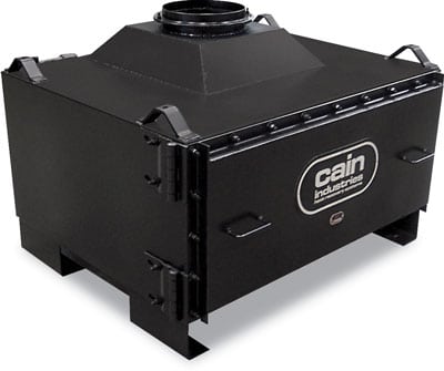


RTR – Rectangluar Tube Recovery Series
The RTR is ideal for large steam boilers and hot water boilers. The RTR is typically used to preheat boiler feedwater, process water, hot oil, or cold water condensing applications. A variety of heat transfer surfaces are available, including: 316L stainless steel, carbon steel, duplex stainless steel, and stainless steel tube with aluminum bonded AL-FUSE™ product (see the example RTR product specification for materials). The exclusive, standard feature, internal stainless steel exhaust gas bypass can be used to temper the exiting gas for stack corrosion control or to maintain water temperatures when too much heat is available.
Combustion Sources
Steam boilers, hot water boilers, and hot oil heaters with inputs up to 250,000,000 BTU/hr.
Boiler Exhaust Application
- Capacity: to 250,000 lb/hr steam
- Entering gas temps: 300°F – 800°F
- Heat sink types: Boiler feedwater, makeup water, hot water return, hot water storage tank, condensate tank, process water

Features
- Internal expansion design
- Most models have no pressure welds in the gas stream
- Mounting flanges for bolting to mating flanges/adapters
- Condensate drain catch ring assembly
- 10 ga. structural exterior
- Stainless steel interior
- 2″ factory insulation
- Removable access doors
- Stainless steel bypass
- Header manifold for high liquid flow
- Exclusive Cain compression fittings between finned tubes and the liquid manifolds for easy tube removal that requires no welding
- Internal stainless steel bypass diverter controls either exiting exhaust gas or liquid temperatures
- Flexible stainless steel hose allows travel of the sootblower carriage
- Sootblower controller maintains air/steam pressure during blowdown operation
Optional Equipment
- Modulating bypass actuator assembly for automatic operation
- Hinged inspection doors for immediate access
- Timed automatic sootblower assembly provides blowdown without scheduling personnel
- Stack corrosion control assembly
- Liquid temperature control assembly
- Structural support stand
Ethanol Plant, Oshkosh, Wisconsin RTR-166K25.7ALS recovering BTU from a 2,200 BHP, steam boiler; Reducing 367°F @ 18,473 SCFM to 299°F; Raising the temperature of 152 gpm of boiler feedwater from 227°F to 245°F.


Installation: structural support stand
Ice Cream Plant, Bakersfield, California RTR-148F26ALS recovering BTU from a 500 BHP, steam boiler; Reducing 430°F @ 4,198 SCFM to 305°F; Raising the temperature of 35 gpm of boiler feedwater from 210°F to 247°F.
Installation: ceiling suspension
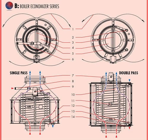
RTR Assembly

- Optional hinged door
- 10 ga. carbon steel exterior
- Stainless steel exhaust gas bypass
- 2″ thick insulation
- Stainless steel interior
- Inspection door for tube cleaning
- Optional RTR-to-stack adapter
- Optional ASME stamp
- 2″ x 2″ gas flange connection
- Removable finned tube rows
- Compression fittings for easy tube removal
- Header manifold
- Optional modulating actuator
- Optional condensate drain catch assembly
Installation for Exact Fit
In many cases, the RTR is designed to replace a competitor’s unit. The RTR will meet or exceed the old performance and at the same time fit within the original stack connections.
Brewery, Ontario, Canada
(1) RTR-1V2Q28CSS recovering BTU from (1) 95,000 pph steam boiler; Re educing 505°F @ 24278 SCFM to 333°F; Raising 196 gpm boiler feedwater entering at 225°F to 278°F.
Variety
One feature of the RTR product line is the large variety of sizes and configurations that are available. Cain Industries routinely produces RTR models that range in application size from small 50 hp boilers to massive 250,000 pph boilers. In addition, RTR units can be engineered to function in a horizontal or vertical stack and can be outfitted with optional automatic sootblowers.

Delivery
Cain Industries keeps strict control over production and delivery scheduling so our customers receive their heat recovery equipment on time and on budget. We routinely ship regionally, nationally, and internationally and keep you informed every step of the way.

RTR: Specification
A general specification, shown as a guide for design & construction. (see Engineering Sales Manual for detailed specification data sheets)
1.0 General Design:
1.1
Furnish and install a rectangular tube recovery (RTR) in the exhaust duct of the boiler in accordance with the following specifications as designed and manufactured by Cain Industries, Inc.
1.2
The RTR shall be a light weight design for easy installation, rectangular with crossflow heat transfer design manufactured and tested in accordance with the requirements of Section VIII, Division 1 of the ASME Boiler and Pressure Vessel Code, and stamped to a minimum 250 PSIG design pressure to the appropriate section.
1.3
Each RTR shall be designed to include as standard, a stainless steel, internal, Flue Gas Bypass Diverter to provide for full emergency by-pass, requiring no additional ductwork for controlling: 1. Stack corrosion, 2. Turn down performance, 3. Back pressure.
1.4
The RTR shall have removable, gas-tight inspection doors providing complete access to the entire heating surface for inspection, tube removal, and/or cleaning (optional hinged doors available).
1.6
The RTR must be capable of being drained completely when mounted in the vertical or horizontal position.
1.7
Header manifolds for low liquid flow pressure drop shall be provided and shall have connections, threaded or flanged as specified. Liquid inlet and outlet pipe connections greater than 2″ NPT shall be flanged. The liquid header manifolds shall also contain 3/4″ NPT connections for venting, draining, and/or safety relief valves as required.
1.8
The design of the vessel itself shall be such that no tube to tube, or tube to header joint welds shall be in contact with the exhaust stream so as to minimize potential vessel failure.
1.9
The finned tubing shall be a single row design (maximum 2 row depth in the direction of the exhaust flow) for ease of cleaning and inspection. Tube to header joint shall be compression tube fittings requiring no welding for fast/easy tube replacement.
2.0 Construction:
2.1
Design Pressure (water side): 250 PSIG @650°F.; Test Pressure: 375 PSIG; Max. Flue Gas Inlet Temperature: (see below); Design Pressure (exhaust side): 3″ water column
2.2
Tube & Fin Designs:
- SA178GrA ERW x 1.0″ OD x .083″ wall thickness with carbon steel .030 Fin thickness x .50 Hgt Nickel Brazed/welded to the tube.
- TP316L x 1.0″ OD x .065″ wall thickness with aluminum .020 fin thickness x .50 hgt AL-FUSE™ bonded to the tube.
- TP316L x 1.0″ OD x .065″ wall thickness with 304 stainless steel .020 Fin thickness x .50 Hgt Nickel Brazed/welded to the tube.
2.3
Compression fitting design: 1000 PSI @ 400°F.
2.4
Headers: thickness: Sch 80; material: SA106 GrB
2.5
2″ thickness factory installed, high temperature insulation shall be contained within the exterior less the liquid headers.
2.6
Exterior surfaces shall be 10ga. carbon steel seam welded and the inner casing shall be 304 stainless steel.
2.7
Special codes (optional): design specifications of ASME Code Section VIII Division I; ‘UM’, ‘U’, or ‘S’ symbol; National Board registered; CRN.
3.0 Optional System Component Equipment:
(see Engineering Sales Manual for optional equipment specifications or contact Cain Industries)
Exhaust Stack Adapters allow the RTR to provide maximum heat recovery while mating perfectly with an existing exhaust stack. Adapters also allow the rectangular RTR to work with a round exhaust stack.
Removable Access Doors provide a complete view of the finned tube heating surface for inspection, repair, or maintenance. This reduces down time and labor expenses.
Mounting Flanges & Adapters are integral to Cain Industries economizers, reducing installation time and providing a superior connection between the existing stack and the Cain unit.
Exterior Liquid Manifolds
maintain very low liquid pressure drop, eliminating the need for extra pumps/HP. This manifold is connected to the finned tubes with compression fittings which allow a finned tube to be removed for inspection or replacement without requiring any welding.
Single Row Finned Tubing design (maximum of 2 rows in the path of the exhaust flow) allows full access to the entire heating surface and provides ease of cleaning and maintenance. Each finned tube row has no welds in the exhaust gas stream which greatly minimizes the chance of tube failure.
Bypass Diverter allows the amount of exhaust gas diverted through the economizer to be modulated to achieve desired heat recovery. This becomes an important safety feature when you recover more heat than required by the existing system.
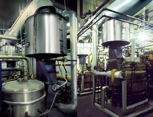
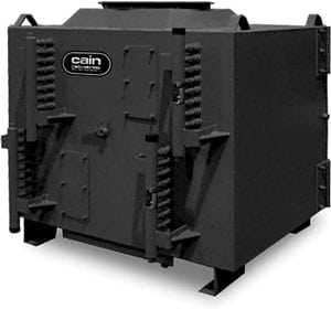
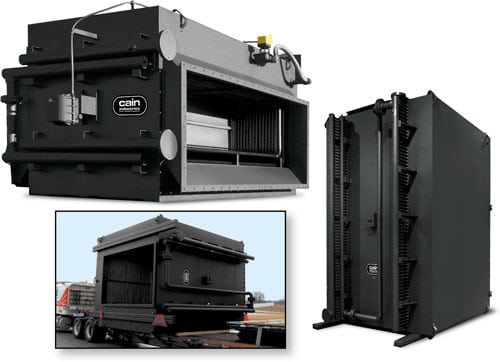
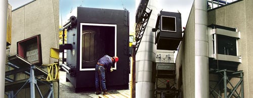
Photo on left:
Vertical flow RTR shown with optional timed automatic sootblower assemblies. This unit uses three sets of traveling carriages with high velocity cleaning nozzles.

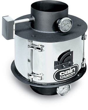
Timed Automatic Sootblower
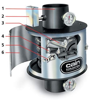
The exclusive Cain Industries Timed Automatic Sootblower design is applied where sulfur content is high or combustion is poor. The special flood-jet type nozzles achieve maximum cleaning velocity using steam or air discharged through an electric control valve. Together they form a ‘continuous knife edge concentrated spray pattern’ surrounding the heating surface. This ‘ring nozzle assembly’ is attached to a manifolded flexible steel hose assembly and is powered back and forth by a pneumatic drive cylinder. Dual timing relays allow full control of cycle duration and interval. Cleaning the finned tubing ensures maximum BTU recovery and maximum cost savings. Fouled finned tubing can reduce heat recovery by up to 50%.

Proper sootblowing is necessary when fuel has a high sulfur content or combustion is poor (such as No. 6 fuel oil). Without sootblowing, the finned tubing will become fouled and the maximum heat recovery cannot be achieved.
The traveling Ring Assembly with Flood-Jet Nozzles, form a unique high velocity knifing action to allow full penetration of the complete heating surface. The Cain Industries sootblowing system is unsurpassed in the marketplace for effectiveness and efficiency.
Built-in timing relays allow you to customize the interval and duration to suit your application.